



How Components Are Loaded into Paper Carrier Tape: Step-by-Step SMT Packaging Guide
Paper carrier tape plays an important role in tape-and-reel packaging for small electronic components. It is widely used for chip resistors, MLCC capacitors, inductors, diodes, and other compact SMT components that need to be delivered in a stable, machine-ready format.
However, components are not simply dropped into the tape. A reliable loading process requires accurate pocket design, controlled component feeding, correct orientation, proper seating, cover tape sealing, inspection, and final reeling. Each step affects how smoothly the components will run through SMT feeders and pick-and-place machines.
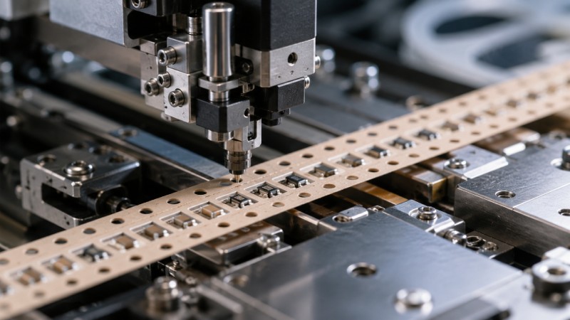
For buyers, understanding how components are loaded into paper carrier tape helps you evaluate whether a supplier can provide stable packaging quality, reduce assembly issues, and support high-volume electronic production.
What Is Paper Carrier Tape Used For?
Paper carrier tape is a continuous strip of paper material with punched cavities designed to hold small electronic components one by one. These cavities keep each component separated, aligned, and protected during storage, transportation, and automated assembly.
After components are loaded into the cavities, the tape is sealed with cover tape and wound onto reels. During SMT production, the reel is placed into a feeder, the cover tape is peeled back, and the pick-and-place machine removes each component from the pocket.
Paper carrier tape is commonly used for small and lightweight SMD components, especially passive components. Typical applications include chip resistors, multilayer ceramic capacitors, small inductors, diodes, and other miniature parts. Compared with plastic embossed carrier tape, paper carrier tape is usually more suitable for thin, flat, and high-volume components where cost efficiency and feeding stability are important.
For taller, thicker, or irregularly shaped components, plastic carrier tape may be a better option because it can provide deeper and more customized pocket shapes.
Quick Answer: How Are Components Loaded into Paper Carrier Tape?
Components are loaded into paper carrier tape by using automated loading equipment that feeds individual parts into punched cavities. Before loading, the tape pockets must match the component size, thickness, and orientation requirements. The components are then guided into each cavity, checked for correct position, sealed with cover tape, inspected, and wound onto a reel.
The basic process usually includes:
-
Confirming component size and orientation
-
Preparing the punched paper carrier tape
-
Feeding components into the loading system
-
Placing each component into the cavity
-
Checking position and direction
-
Applying cover tape
-
Reeling and final inspection
A well-controlled loading process helps ensure that components remain stable in the tape and can be picked accurately during SMT assembly.
Step 1: Confirming Component Size, Shape, and Orientation
Before components can be loaded into paper carrier tape, the supplier must first confirm the component dimensions and packaging requirements. This includes the component length, width, thickness, shape, weight, and tolerance range.
The most important cavity-related dimensions are usually A0, B0, and K0. In simple terms, A0 refers to the cavity width, B0 refers to the cavity length, and K0 refers to the cavity depth or thickness clearance. These dimensions must be designed carefully so the component can sit inside the pocket without being too tight or too loose.
If the pocket is too small, the component may not enter smoothly or may become damaged during loading. If the pocket is too large, the component may rotate, tilt, or shift during transportation and feeding.
Orientation is also important. For non-polarized passive components, the main concern is usually stable seating. For polarized components, marked components, or components with a specific mounting direction, the orientation must be clearly defined before loading begins. Incorrect orientation can cause serious problems during assembly, especially when the SMT machine expects every component to face the same direction.
Step 2: Preparing the Paper Carrier Tape
Once the component requirements are confirmed, the paper carrier tape must be prepared. Paper carrier tape pockets are usually created by a punching process. The cavities must be clean, consistent, and accurately positioned along the tape.
The quality of the punched cavities directly affects the loading result. If the pocket edges are rough, if the cavities are inconsistent, or if paper dust remains inside the tape, the components may not sit properly. In high-speed packaging, even small defects can lead to empty pockets, tilted parts, or unstable feeding.
Sprocket holes are another key part of the tape design. These holes allow the tape to advance accurately through packaging equipment and SMT feeders. If sprocket holes are not stable or accurately spaced, the tape may not align correctly with the loading head or the pick-and-place machine.
Before mass loading, the tape should be checked for pocket accuracy, hole position, surface cleanliness, and winding condition. Good tape preparation reduces problems before components even enter the loading system.
Step 3: Feeding Components into the Loading System
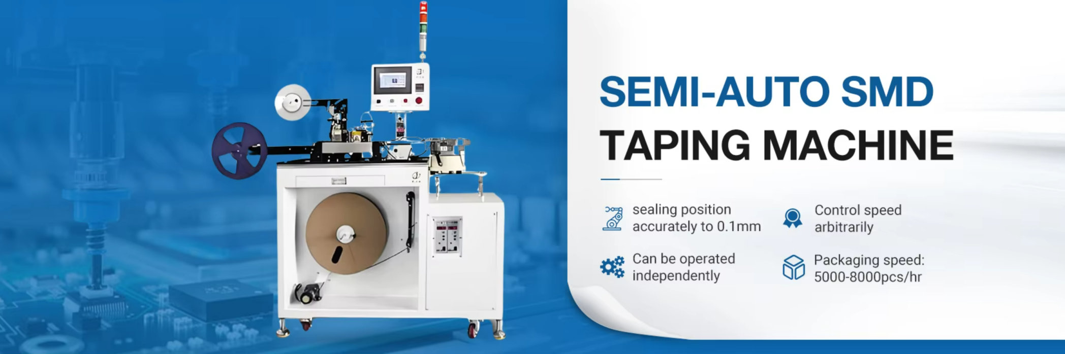
After the paper carrier tape is prepared, components must be supplied to the loading machine in a controlled way. For many small passive components, automated feeding systems are used to separate bulk components and guide them toward the loading position.
One common method is vibratory bowl feeding. In this system, components are placed into a bowl that vibrates in a controlled pattern. The vibration separates the components and moves them along a track. The track helps guide the components into the correct position before they are loaded into the tape.
For some components, linear feeders or track feeding systems may be used. These systems move components in a controlled line so the loading equipment can pick or guide each part into the paper tape cavity.
Not every component can be handled the same way. Fragile components, unusual shapes, special polarity requirements, or low-volume production may require a customized feeding method. In these cases, the supplier may need to adjust the feeding track, loading speed, or transfer mechanism to protect the component and maintain accurate orientation.
Step 4: Placing Components into Each Paper Tape Cavity
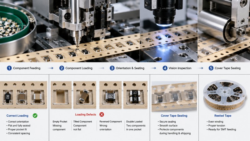
The actual loading step happens when each component is placed into the punched cavity of the paper carrier tape. The tape advances pocket by pocket, and the loading head transfers or guides the component into the correct position.
A correctly loaded component should sit flat inside the cavity. It should not stand upright, tilt, rotate excessively, or protrude above the tape surface. Each pocket should contain only one component, and every required pocket should be filled.
This step is critical because loading accuracy directly affects SMT performance. If a component is not seated correctly, the pick-and-place nozzle may fail to pick it up. If the component rotates inside the pocket, the machine may reject it or place it incorrectly. If a pocket is empty, the assembly line may experience missing-component defects. If two components are loaded into one pocket, the feeder or pick-and-place system may stop or generate errors.
For buyers, this is one of the most important parts of the process to evaluate. A paper carrier tape supplier should not only manufacture the tape but also understand how pocket design and loading quality affect downstream assembly performance.
Step 5: Checking Component Orientation and Position
After components are loaded into the cavities, their position and orientation must be checked. Depending on the production volume and quality requirements, inspection may be done visually, automatically, or through a combination of both.
Automated camera inspection is commonly used for high-volume production. Vision systems can detect common loading problems such as empty pockets, reversed parts, tilted components, double-loaded pockets, damaged components, contamination, or incorrect orientation.
For simple passive components, the key inspection points are usually seating stability, pocket filling, and component movement. For polarized components or marked parts, directional control becomes much more important.
Inspection should happen before cover tape sealing whenever possible. Once the cover tape is applied, it becomes harder to correct a loading defect without removing or reworking the tape. Early inspection helps reduce waste and prevents defective reels from reaching the customer.
Step 6: Applying Cover Tape After Loading
Once the components are correctly loaded and inspected, cover tape is applied over the paper carrier tape. The cover tape keeps components inside the cavities during winding, shipping, storage, and SMT feeding.
Cover tape can be applied through heat sealing or pressure sealing, depending on the tape type, component requirements, and packaging process. The sealing strength must be carefully controlled. If the seal is too weak, components may escape from the pockets during handling or transportation. If the seal is too strong, the cover tape may not peel smoothly during SMT assembly.
Peel performance is especially important. During SMT feeding, the cover tape must peel away consistently without shaking the components out of position. Poor peel force can lead to feeder jams, component movement, or unstable pick-up.
A reliable supplier should match the paper carrier tape, cover tape, and sealing conditions based on the component type and customer’s assembly requirements.
Step 7: Reeling and Final Packaging
After cover tape sealing, the loaded tape is wound onto reels. Reeling must be controlled carefully because winding tension can affect tape shape and component stability.
If the tape is wound too tightly, the carrier tape may deform, and components may experience pressure inside the cavities. If the tape is too loose, the reel may become unstable during shipping or feeding. The goal is to keep the tape flat, evenly wound, and easy to feed into SMT equipment.
Leader and trailer sections are often added before and after the loaded portion of the tape. These empty sections help operators set up the reel in the feeder and allow the machine to begin feeding smoothly before reaching the first loaded component.
Final packaging may include labeling, moisture protection if required, outer cartons, and handling instructions. For export shipments or long-distance transportation, reel protection is also important to prevent bending, compression, or contamination.
Key Quality Checks During Paper Carrier Tape Loading
A good paper carrier tape loading process includes several quality checks. These checks help ensure that the finished reel is suitable for automated SMT production.
| Quality Check | What It Confirms | Why It Matters |
|---|---|---|
| Pocket size check | Cavities match component dimensions | Prevents tight fit or loose movement |
| Orientation check | Components face the correct direction | Reduces assembly errors |
| Seating check | Components sit flat in the pocket | Improves pick-up reliability |
| Empty pocket check | Each required pocket is filled | Prevents missing components |
| Double-load check | Only one component is placed per cavity | Avoids feeder and placement errors |
| Cover tape seal check | Cover tape is properly sealed | Keeps components secure |
| Peel force check | Cover tape peels smoothly | Supports stable SMT feeding |
| Reel winding check | Tape is wound evenly | Prevents feeding jams |
These checks are important because defects can come from both the tape and the loading process. Even if the paper carrier tape is well manufactured, poor loading can still cause serious assembly problems.
Common Problems When Components Are Loaded Incorrectly
Incorrect loading can create several issues. One common problem is component rotation. This often happens when the cavity is too large or the component shape is not well controlled inside the pocket. Excessive rotation may lead to poor pick-up accuracy.
Another issue is tilted or standing components. If a component does not sit flat, the pick-and-place nozzle may not pick it correctly. This can cause rejection, downtime, or placement defects.
Empty pockets and double-loaded pockets are also serious quality problems. Empty pockets can lead to missing parts on the PCB, while double-loaded pockets may jam the feeder or cause machine errors.
Cover tape problems can also affect the final result. Weak sealing may allow components to move or fall out, while excessive sealing may cause poor peeling performance. For stable SMT assembly, the entire packaging system must work together: paper tape, pocket design, component loading, cover tape sealing, and reel winding.
Paper Carrier Tape Loading vs Plastic Carrier Tape Loading
Paper carrier tape and plastic carrier tape are loaded in similar general steps, but the pocket structure is different.
Paper carrier tape uses punched cavities and is usually best for small, thin, flat components. It is cost-effective and efficient for high-volume passive component packaging. The main concerns are pocket accuracy, paper dust control, component seating, and movement inside the cavity.
Plastic carrier tape usually uses embossed pockets. It is more suitable for taller, thicker, or irregular components because the pocket shape and depth can be more flexible. It is often used for ICs, connectors, sensors, modules, and components that require deeper cavities or stronger mechanical protection.
The right choice depends on component size, shape, thickness, sensitivity, and SMT feeding requirements. Buyers should not select paper or plastic tape based only on price. The better option is the one that keeps the component stable and supports reliable assembly.
What Buyers Should Confirm Before Ordering Paper Carrier Tape Loading
Before ordering paper carrier tape or tape-and-reel packaging, buyers should prepare several key details.
First, provide the component drawing or physical samples. This helps the supplier confirm the component dimensions, tolerances, polarity, and handling requirements.
Second, confirm the required tape width, pitch, pocket size, and reel quantity. For small passive components, common tape formats may be available, but custom pocket design may still be needed for special sizes.
Third, define the loading direction and orientation. This is especially important for polarized components or components with markings. Clear orientation requirements help avoid assembly mistakes later.
Fourth, confirm the cover tape type and peel force expectations. The cover tape must protect the components during shipping while still peeling smoothly during SMT feeding.
Finally, request sample testing before mass production. A trial run allows both the buyer and supplier to check component seating, pocket fit, cover tape sealing, reel winding, and feeder compatibility before committing to large-volume production.
Conclusion
Loading components into paper carrier tape is a controlled packaging process, not a simple placement step. It requires accurate cavity design, stable component feeding, correct orientation, careful seating, proper cover tape sealing, inspection, and controlled reeling.
When the process is done correctly, paper carrier tape can provide efficient, reliable, and cost-effective packaging for small SMT components. When it is done poorly, the result may be component rotation, empty pockets, feeder jams, poor pick-up performance, and assembly downtime.
If you need paper carrier tape for small electronic components, choose a supplier that understands both tape manufacturing and component loading requirements. This helps reduce packaging risk and supports smoother SMT production.
FAQs About Loading Components into Paper Carrier Tape
What components are suitable for paper carrier tape?
Paper carrier tape is commonly used for small, thin, and lightweight SMT components such as chip resistors, MLCC capacitors, small inductors, diodes, and similar passive components.
Are components loaded manually or automatically?
High-volume production usually uses automated loading equipment. Manual handling may be used for samples, testing, or special low-volume requirements, but automated loading is preferred for consistency and efficiency.
Why do components rotate inside paper carrier tape?
Component rotation may happen when the cavity is too large, the component shape is unstable, or the pocket design does not match the component properly. Correct A0, B0, and K0 design helps reduce rotation.
What happens after components are loaded into the tape?
After loading, the tape is sealed with cover tape, inspected, wound onto reels, labeled, and packed for delivery or SMT assembly.
Can paper carrier tape be customized for different components?
Yes. Paper carrier tape can be customized by adjusting pocket size, tape width, pitch, sprocket hole layout, orientation requirements, cover tape type, and reel format.
How do I know whether paper carrier tape or plastic carrier tape is better?
Paper carrier tape is usually better for small and flat passive components. Plastic carrier tape is often better for thicker, taller, heavier, or irregularly shaped components that need deeper or more protective pockets.



 Emial
Emial John Mr