Carrier Tape Materials Guide: PC vs PS vs PET vs Paper for SMT Packaging
Why Carrier Tape Material Selection Matters in SMT Packaging
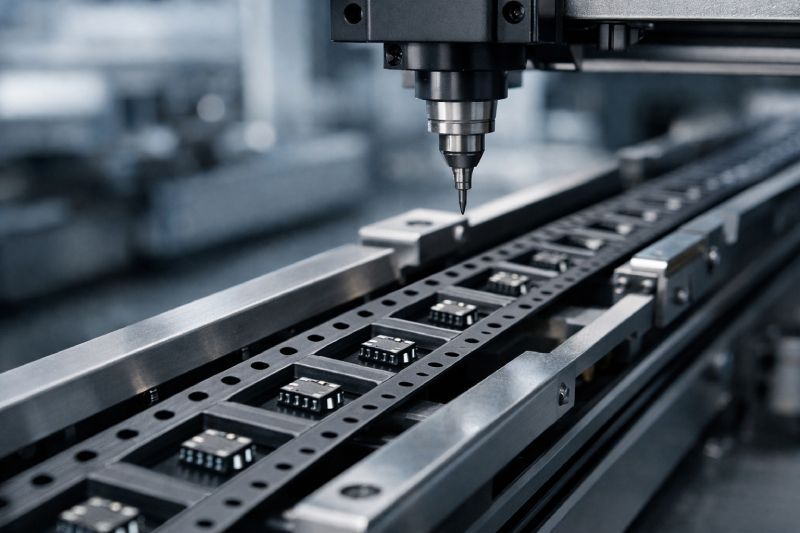
In SMT packaging, carrier tape material selection directly determines process stability, not just unit cost. The material defines how consistently pockets can be formed, how well their geometry is retained over long production runs, and how reliably components are presented to automated pick-and-place systems. Even small material-related deviations—such as pocket deformation, insufficient rigidity, or inconsistent recovery after forming—can lead to feeding interruptions, mis-picks, or component damage.
From an engineering perspective, material choice influences pocket accuracy, pitch consistency, and long-term dimensional stability under real SMT conditions. These factors directly affect line speed, placement accuracy, and overall yield. Selecting the wrong material often introduces hidden risks: increased downtime, higher defect rates, and unstable automation performance that outweigh any initial material cost savings.
This is why carrier tape material selection should be treated as an engineering decision, closely aligned with component characteristics and packaging design requirements, rather than a price-driven choice.
Common Materials Used in Carrier Tape
Carrier tape materials can be broadly grouped by their forming behavior, mechanical stability, and suitability for different SMT packaging conditions. Each material serves a specific engineering role, and understanding this material landscape is the foundation for correct selection—before any comparison or recommendation is made.
PC (Polycarbonate) is widely used in applications that demand high forming precision and dimensional stability. Its mechanical strength and thermal resistance allow it to maintain pocket geometry across complex designs and long production runs, making it common in precision-driven packaging scenarios.
PS (Polystyrene) is typically chosen for cost-sensitive projects. It offers good formability and clarity under controlled conditions, but its mechanical limits define where it can and cannot be applied in SMT environments.
PET sits between PC and PS in both performance and cost. It provides a balanced option where moderate stability is required without the higher material rigidity of PC, often used for standard components with reasonable tolerance margins.
Paper carrier tape represents a specialized category rather than a mainstream solution. It is primarily used for small, lightweight, and flat components operating under low-speed SMT conditions.
This overview establishes a material map—not a ranking. Each option aligns with different component characteristics, process requirements, and packaging constraints, which are explored in detail in the following sections.
Polycarbonate (PC) Carrier Tape
Polycarbonate (PC) is widely regarded as the benchmark material for high-precision embossed carrier tape. From an engineering standpoint, its primary advantage lies in forming accuracy and repeatability. PC maintains stable pocket geometry even in complex designs involving deep cavities, sharp corner definitions, or tight tolerance requirements. This consistency is critical when packaging micro-components or irregularly shaped parts that rely on precise pocket support for positional stability.
PC also performs reliably under high-speed SMT conditions. Its rigidity and thermal resistance help pockets retain dimensional accuracy throughout long production cycles, reducing deformation caused by continuous feeding, vibration, or environmental variation. As a result, feeding reliability and pick-and-place accuracy remain stable over time, supporting higher line speeds and yield targets.
It is important to clarify that PC’s value is not its price point, but its stability. While often perceived as a “premium” option, PC is typically selected to mitigate process risk, protect component integrity, and ensure repeatable automation performance—especially where failure costs are high.
Polystyrene (PS) Carrier Tape
Polystyrene (PS) carrier tape is commonly used where cost control is a primary constraint, and its engineering boundaries are clearly understood. PS offers good initial formability and can achieve acceptable pocket definition for simple geometries, making it suitable for standard components with relatively loose tolerance requirements.
However, PS has inherent mechanical and thermal limitations. Compared to PC, it is less rigid and more sensitive to deformation, especially under higher SMT speeds or extended production runs. Pocket dimensional consistency may degrade over time, which can affect feeding stability and placement accuracy if process margins are tight.
From an application perspective, PS is best suited for low- to medium-speed SMT lines, simpler pocket designs, and components that are mechanically robust. It is not recommended for micro-components, complex pocket structures, or high-yield, high-speed production environments where process stability is critical.
PET Carrier Tape
PET carrier tape is generally positioned as an engineering compromise between PC and PS, balancing material cost with acceptable mechanical stability. From a forming perspective, PET offers better dimensional retention than PS while remaining more economical than PC, making it a practical option for many standard SMT applications.
In production, PET can achieve consistent pocket geometry for moderate depths and relatively simple designs. Its stiffness supports stable feeding under controlled SMT speeds, and its resistance to creep is sufficient for components that do not impose extreme structural demands on the pocket. As a result, PET is often selected for projects where process stability is required, but ultra-tight tolerances are not.
That said, PET is not designed for high-risk or extreme-precision scenarios. For very small components, complex pocket profiles, or high-speed lines with minimal process margin, PET may approach its performance limits. In these cases, materials with higher rigidity and forming repeatability are typically preferred.
Paper Carrier Tape
Paper carrier tape is a specialized solution designed for specific, limited applications, rather than a mainstream SMT packaging material. Its structure and forming method differ fundamentally from plastic carrier tapes, which defines both its advantages and its constraints.
From an engineering perspective, paper carrier tape is typically used for small, lightweight, and flat components where pocket depth requirements are minimal. It performs best in low-speed SMT environments, where feeding forces are controlled and automation stress on the tape is relatively low. In these scenarios, paper tape can provide adequate component retention and transport stability.
However, paper lacks the structural rigidity and dimensional precision required for complex pocket geometries or high-speed production lines. Moisture sensitivity, limited tolerance control, and reduced durability make it unsuitable for applications demanding tight dimensional consistency or long-term feeding stability.
For these reasons, paper carrier tape should be viewed as an application-driven option, selected only when component characteristics and process conditions align with its inherent limitations.
Conductive Carrier Tape Materials for ESD Protection
In certain SMT packaging scenarios, standard carrier tape materials are electrically insufficient, making ESD-driven material selection a critical engineering requirement rather than an optional upgrade. This is especially true for sensitive semiconductor devices, ICs, LEDs, and MEMS components where uncontrolled static discharge can cause latent or immediate failure.
Conductive carrier tape materials are engineered to provide a controlled and continuous discharge path, ensuring that electrostatic charge is safely dissipated throughout handling, transport, and automated feeding. This is fundamentally different from antistatic materials, which only reduce charge generation but do not actively conduct accumulated charge away. In high-risk environments, antistatic solutions alone may not offer adequate protection.
From an engineering standpoint, the decision to use conductive carrier tape is driven by ESD risk exposure, not by component size or cost. Factors such as device sensitivity level, handling frequency, and SMT line grounding strategy all influence this choice. When ESD failure carries high reliability or warranty risk, conductive materials become a process safeguard rather than a material preference.
How to Choose the Right Carrier Tape Material for Your Application
Choosing the right carrier tape material is an engineering judgment process, not a selection exercise based on material labels or price tiers. The correct decision starts with understanding how the component interacts with the pocket and how that pocket performs throughout the entire SMT process.
Component size and fragility define the baseline. Smaller, thinner, or more delicate components require materials that can hold tighter pocket tolerances and resist deformation during feeding. Pocket complexity further narrows material options—deep cavities, fine corner radii, or asymmetrical designs demand higher forming stability.
SMT line speed and automation intensity are equally critical. As feeding speed increases, material rigidity and recovery behavior become decisive factors in maintaining pitch accuracy and preventing mis-picks. For ESD-sensitive devices, electrical performance overrides mechanical considerations, making conductive or controlled-dissipation materials mandatory.
Finally, production volume and yield expectations determine acceptable risk. High-volume programs amplify small inconsistencies into systemic losses, favoring materials with proven long-term stability.
How Material Choice Affects Manufacturing & Quality
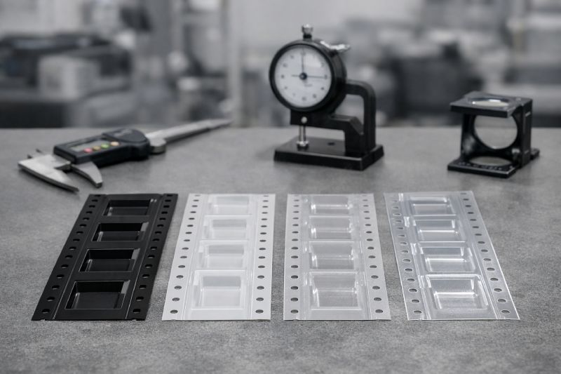
Carrier tape material selection has a direct impact on manufacturing consistency and quality control outcomes. During forming, material behavior determines how accurately pocket dimensions can be reproduced from cavity to cavity and from batch to batch. Materials with stable thermal and mechanical properties allow tighter control over forming parameters, reducing variation across long production runs.
From a tolerance standpoint, material rigidity influences how well pocket geometry is maintained after forming, slitting, and winding. Insufficient stability can introduce subtle dimensional drift, which may not be immediately visible but can affect feeding reliability and component positioning during SMT assembly.
At scale, these effects compound. A material that performs acceptably in small batches may show variability when production volumes increase. This is why material choice is closely tied to yield performance and process capability indices, especially for automated, high-throughput packaging programs.
Summary
Carrier tape material selection should always be guided by application requirements, not material price or familiarity. Each material—PC, PS, PET, paper, or conductive variants—offers a different balance of forming stability, mechanical performance, and process risk. The correct choice depends on how the component behaves in the pocket and how that pocket performs under real SMT conditions.
From an engineering standpoint, stable automation, consistent feeding, and predictable yield are driven by material behavior over time, not by short-term cost savings. Treating material selection as a process decision rather than a purchasing decision is key to long-term reliability.
If you are evaluating material options for a specific component or SMT environment, the next step is to align material properties with your actual process constraints.

 Emial
Emial John Mr